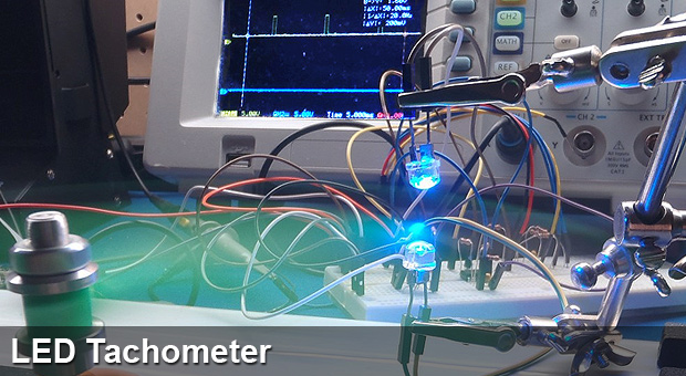
Hello friends and welcome to my guide on how NOT to make a tachometer. A tachometer is a device that reads RPM. The story behind this is I needed a tachometer and I didn’t have the ideal components to make one so I made do with what I had. Here are the circuit contents:
Rough Component List:
1x LM358
Xx 1k, 10k, 100k 1/4W Resistors
Xx 1uF Caps
1x Helping Hands
2x LEDs
1x NPN
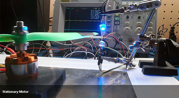
Principle of operation: Most transducers (speakers, motors…ect) work as “generators”. The same is true with LEDs. I wanted to use a LED as a sensor and another LED of the same type as a transmitter. However, since a given LED isn’t designed to work as a photo-diode, it is a very poor sensor. None the less, with a bit of effort you can make it work! First step is to amplify the small bit of excitation power the LED produces when a LED of the same wavelength is shined at it. To do this, I selected a NPN BJT. The signal gain was not large enough so I used a darlington configuration. Below is the circuit + scope shot with propeller spinning.
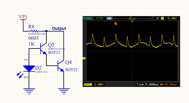
Again, above is the circuit and scope shot of the output. When the rotor passes inbetween the 2 LEDs, the lower LED no longer receives power and consequently shuts off the NPN pair. When the NPNs are shutoff, the output is pulled high by the open collector pullup resistor(R8). Notice we have 60Hz coupled onto the output in addition to some spikes. The spikes a course are when the rotor passes over the LED. This signal by itself is rather crappy and hard to read with a microcontroller. We want to turn these spikes into nice puleses that our MCU can easily read via a GPIO pin. Looking ahead, using a comparator, we should be able to find the peaks and generate pulses for the tachometer. However, the reference is somewhat messy for the comparator because of the DC offset on the signal. Next step is to create a simple high pass filter to block the DC Offset.
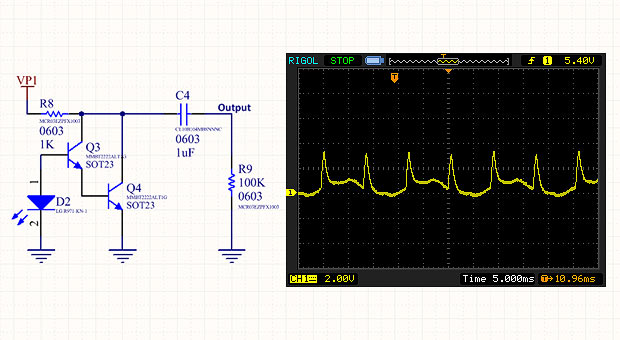
Now that the DC is blocked, we still need a reference for our comparator. The problem with a fixed voltage is that the spike output voltage will vary with respect to speed. Consequently, using the average of the signal is ideal. To average the signal we use a very low cutoff frequency low pass filter. Next I wired an op amp in a comparator configuration.
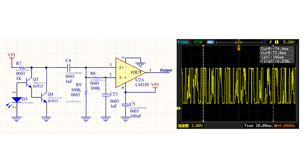
At this point, your probably thinking i’m trolling you which… well trying to use an LED for this application is abit trollish. Anyhow, the reason the output is pure garbage is because of the low frequency content of the signal is periodically crossing our averaged reference and is very noisy. This is why you almost never use a comparator without having a hysteresis region. Add some good ole positive feedback to create a hysteresis region. This will eliminate any small signals from creating a pulse on the output of our op amp.
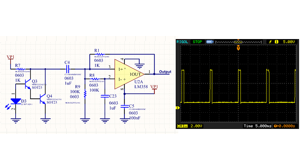
Thats a tad better. Look mom, no photodiode! A course, from here its peanuts to get a MCU hooked up and counting the pulse timings. A simple GPIO interrupt rising edge interrupt + timer would do the trick. I needed this tachometer with a voltage output in order to do frequency verification of my “ESC”(sensorless BLDC controller). To convert this signal to RPM its simply 2 / (Time Between Rising edge interrupts) * 60. Anyhow, thought ya might find this interesting.
Thanks,
Nate